Overview
[ Top
| MIO-R2, v. B
| MIO-R2, v. C
| MIO-R, v. A
| MIO-R, v. B
| Return to Racks
]
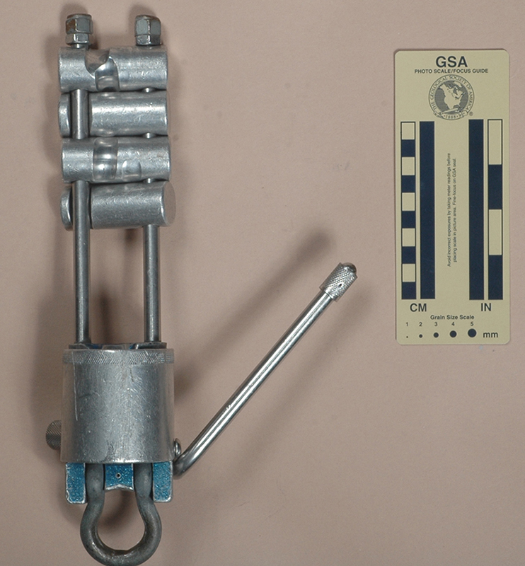
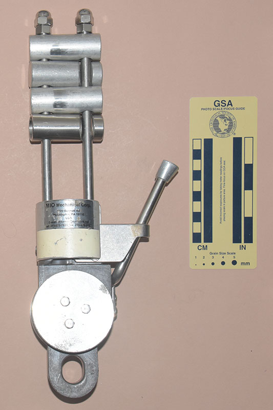
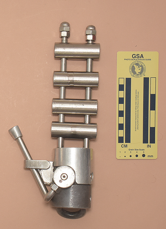
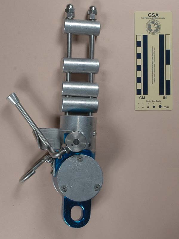
MIO-R2, Version A
(#1459)
Technical Details
I acquired this rack from Don Stephens in 2015.
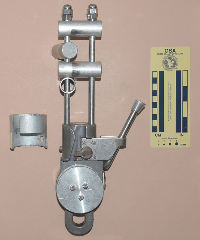
My Mio Mechanical MIO-R2, Version A rack is 300 mm. tall, 163 mm. wide, 80 mm. thick, and weighs 1382 g.
The following description is based on the one for Version B, with common descriptions in gray and changes in black:
Version A consists of an upper four-bar rack portion, a central
lever brake control assembly, and a lower clevis eye.
The rack portion consists of two 181 mm. tall, 9.5 mm.
diameter stainless steel rods screwed into the top of the aluminum
brake assembly housing. The rods are separated by 29 mm.
There are four 61 mm. long, 25 mm. diameter solid aluminum
brake bars. These top and third bar are drilled but not slotted,
so they do not open. The second and fourth bars are slotted, and
hinge on the rod furthest from the brake lever. A stainless steel
hex nut and a stainless steel acorn nut on each rod hold the bars
in place.
The lever brake housing is an 88 mm. tall quasi-cylindrical
section. The upper 56 mm. are 53.7 mm. in diameter,
the remainder 59.1 mm. The bottom 28 mm. has a chordal
sector removed, and two slots cut to accept a 9.5 mm. clevis
(held by a 9.6 mm. pin) that serves as the attachment point. There
is another rounded area removed at the base. A 10 mm. rope
groove cuts through the upper 53.7 mm. portion, sloping down
and left until it intersects the chordal cutout.
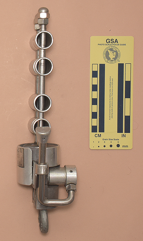
The rear of the upper cylinder has a 28 mm. round-end
milled slot. This slot accepts a 9.6 mm. shaft that serves
as an axle and a 38 mm. long, 25.3 mm./31.8 mm.
diameter stepped bushing that serves as a mount for the brake
lever. There is a washer between the bushing and main body of
the device. A 9.6 mm. diameter, 132 mm. long lever screws
into a bushing mounted on the shaft. The lever bends forward 90°
and then upward at a second, 100° bend. The end of the lever
has an 18.6 mm. tall, 12.7 mm. knurled sleeve pinned to it. A
moderately strong spring forces the lever outward, where a bend
in the stainless steel plate stops its travel.
The front end of the lever axle shaft passes through a stainless
steel plate screwed to the front of the cylindrical section (at
another cutout), where it is welded to a D-shaped cam. The lever
spring holds the cam against the rope. Squeezing the lever toward
the central column rotates the cam away from the rope.
Finally, there is an 8.5 mm. spring-loaded cover retaining
pin on the right side of the base of the lever, and a guide screw on the other side.
The cover is made from 2.85 mm. sheet aluminum rolled into a
near-cylinder, with a 15.5 mm. gap for inserting the rope.
The cover is 61.0 mm. long and its internal diameter is 55.3 mm.
A subrectangular cutout near the bottom (adjacent to the rope
entry groove) allows the cover to clear the lever assembly. A
beveled 9.1 mm. hole aligns with the cover retaining pin.
The cover has a small screw that engages an inverted L-shaped
slot in the lever brake housing. This keeps the cover attached
to the device. The cover does not move smoothly, probably because
the blue paint on the lever brake housing causes the cover to
stick.
One side of the clevis is forged with "T12," "1T,"
"CHICAGO USA," and "3/8."
I acquired this version after the following one, but the lack of the plate limiting the lever movement makes me think this is the earlier model. Other major difference are the shapes of the brake housing, the cover, and the lever knob. None of these differences result in performance differences.
[ Top
| MIO-R2, v. A
| MIO-R2, v. C
| MIO-R, v. A
| MIO-R, v. B
| Return to Racks
]
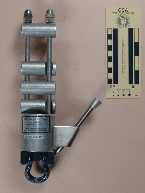
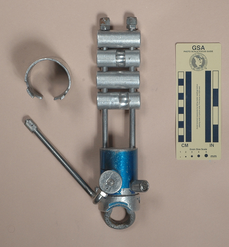
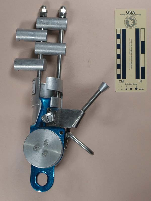
MIO-R2, Version B
(#1066)
Technical Details
I acquired my MIO-R2, Version B from CWC Supply in 2007.
This rack is 299 mm. tall, 142 mm. wide, 81 mm. thick, and weighs 1397 g.
Version B consists of an upper four-bar rack portion, a central
lever brake control assembly, and a lower clevis eye.
The rack portion consists of two 175 mm. tall, 9.5 mm.
diameter stainless steel rods screwed into the top of the aluminum
brake assembly housing. The rods are separated by 29 mm.
There are four 61 mm. long, 25 mm. diameter solid aluminum
brake bars. These top and third bar are drilled but not slotted,
so they do not open. The second and fourth bars are slotted, and
hinge on the rod furthest from the brake lever. A stainless steel
hex nut and a stainless steel acorn nut on each rod hold the bars
in place.
The lever brake housing is an 87 mm. tall quasi-cylindrical
section. The upper 56 mm. are 53.7 mm. in diameter,
the remainder 58.4 mm. The bottom 28 mm. has a chordal
sector removed, and two slots cut to accept a 9.5 mm. clevis
(held by a 9.6 mm. pin) that serves as the attachment point. There
is another rounded area removed at the base. A 10 mm. rope
groove cuts through the upper 53.7 mm. portion, sloping down
and left until it intersects the chordal cutout.
The rear of the upper cylinder has a 28 mm. round-end
milled slot. This slot accepts a 9.6 mm. shaft that serves
as an axle and a 38 mm. long, 25.3 mm./31.8 mm.
diameter stepped bushing that serves as a mount for the brake
lever. There is a washer between the bushing and main body of
the device. A 9.6 mm. diameter, 132 mm. long lever screws
into a bushing mounted on the shaft. The lever bends forward 90°
and then upward at a second, 100° bend. The end of the lever
has an 18 mm. tall, 12.7 mm./20.3 mm. diameter
tip shaped like the frustum of a cone with one side removed. A
moderately strong spring forces the lever outward, where a bend
in the stainless steel plate stops its travel.
The front end of the lever axle shaft passes through a stainless
steel plate screwed to the front of the cylindrical section (at
another cutout), where it is welded to a D-shaped cam. The lever
spring holds the cam against the rope. Squeezing the lever toward
the central column rotates the cam away from the rope.
Finally, there is an 8.5 mm. spring-loaded cover retaining
pin on the side opposite the lever.
The cover is made from 3.0 mm. sheet aluminum rolled into a
near-cylinder, with a 12.7 mm. gap for inserting the rope.
The cover is 63.6 mm. long and its internal diameter is 54.1 mm.
A subrectangular cutout near the bottom (adjacent to the rope
entry groove) allows the cover to clear the lever assembly. A
beveled 9.1 mm. hole aligns with the cover retaining pin.
The cover has a small screw that engages an inverted L-shaped
slot in the lever brake housing. This keeps the cover attached
to the device. The cover does not move smoothly, probably because
the blue paint on the lever brake housing causes the cover to
stick.
One side of the clevis is forged with "T12," "1T,"
"CHICAGO USA," and "3/8."
The cover has two stickers. The smaller sticker says "Pat.
No. 6,814,185" (with quotes). The larger reads as follows:
MIO Mechanical Corp.
2020 Bennett Road
Philadelphia, PA 19116
USA
E-mail: msemio@earthlink.net
Tel: 215-676-7828 fax:215-676-5199
This is an unusual rack. Most cavers and climbers might think
that the MIO-R2 is an odd design, and I would agree with those
who think that it is too heavy, but the MIO-R2 was designed for
industrial use. I acquired mine from a window cleaning supplier,
and it appears that window cleaners are a major part of the target
market for the MIO-R2. Working all day with both hands while hanging
on rope is not the same as rappelling another virgin pit while
exploring an new cave, or rapping off a first ascent. These differences
justify the device.
The spring loaded plunger assembly on my MIO-R2 fell out each
time I opened the cover, so I had to repair this by enhancing
the factory crimps with a punch. This lack of quality control
is disturbing.
The MIO-R2 came with a rather nice 13 page manual. The manual
targets window washers, and shows some typical roof top rigging
setups. There are some nice photographs of the device, both alone
and partially rigged for descent, preceded by detailed illustrated
instructions on how to use the device. Rigging is straightforward:
open the cover, open the cam by depressing the lever, insert the
rope, close the cover, and then zigzag the rope through the bars.
The manual includes a table recommending three rope types,
none of which match normal caving or climbing rope.
The manual indicates that my MIO-R2 is serial number 7442,
but I cannot find that number marked on the device.
[ Top
| MIO-R2, v. A
| MIO-R2, v. B
| MIO-R, v. A
| MIO-R, v. B
| Return to Racks
]
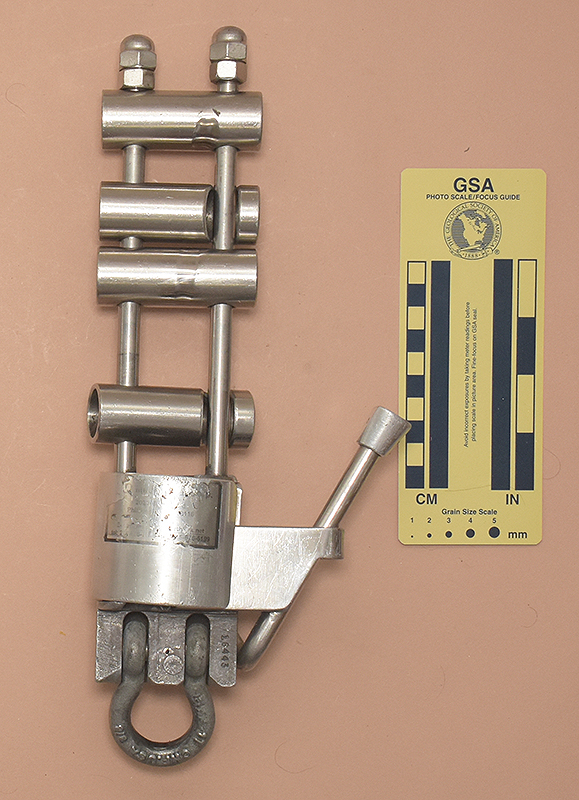
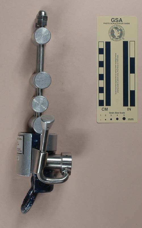
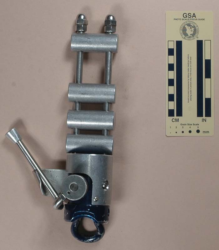
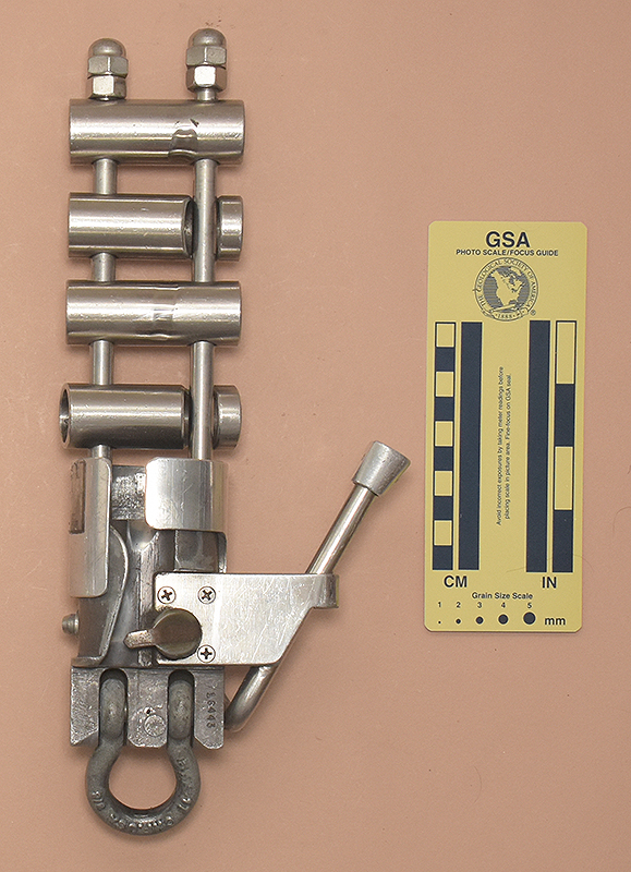
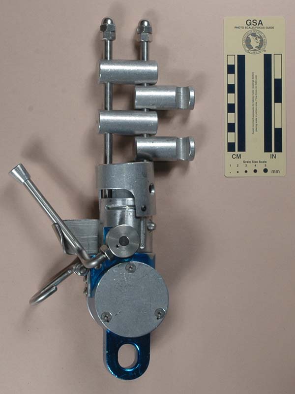
MIO-R2, Version C
(#3321)
Technical Details
I acquired this rack from MX Pawn in 2023.
My Mio Mechanical MIO-R2, Version C rack is 319 mm. tall, 133 mm. wide, 81 mm. thick, and weighs 1384 g.
The following description is based on the one for Version B, with common descriptions in gray and changes in black:
Version B consists of an upper four-bar rack portion, a central
lever brake control assembly, and a lower clevis eye.
The rack portion consists of two 180 mm. tall, 9.5 mm.
diameter stainless steel rods screwed into the top of the aluminum
brake assembly housing. The rods are separated by 29 mm.
There are four 67 mm. long, 25 mm. diameter, 2.5 mm. wall tubular stainless steel brake bars. These top and third bar are drilled but not slotted,
so they do not open. The second and fourth bars are slotted, and
hinge on the rod furthest from the brake lever. A stainless steel
hex nut and a stainless steel acorn nut on each rod hold the bars
in place. A 2.5 mm. hole drilled through the left rod 30 mm. above the brake housing has a split pin that restricts the vertical motion of the lower bar.
The lever brake housing is an 87 mm. tall quasi-cylindrical
section. The upper 56 mm. are 53.7 mm. in diameter,
the remainder 58.4 mm. The bottom 28 mm. has a chordal
sector removed, and two slots cut to accept a 9.5 mm. clevis
(held by a 9.6 mm. pin) that serves as the attachment point. There
is another rounded area removed at the base. A 10 mm. rope
groove cuts through the upper 53.7 mm. portion, sloping down
and left until it intersects the chordal cutout.
The rear of the upper cylinder has a 28 mm. round-end
milled slot. This slot accepts a 9.6 mm. shaft that serves
as an axle and a 38 mm. long, 25.3 mm./31.8 mm.
diameter stepped bushing that serves as a mount for the brake
lever. There is a washer between the bushing and main body of
the device. A 9.6 mm. diameter, 132 mm. long lever screws
into a bushing mounted on the shaft. The lever bends forward 90°
and then upward at a second, 100° bend. The end of the lever
has an 18 mm. tall, 12.7 mm./20.3 mm. diameter
tip shaped like the frustum of a cone with one side removed. A
moderately strong spring forces the lever outward, where a bend
in the stainless steel plate stops its travel.
The front end of the lever axle shaft passes through a stainless
steel plate screwed to the front of the cylindrical section (at
another cutout), where it is pinned to a cam assembly The cam consists of a cylindrical knob with a milled slot. The cam proper is a piece of 6 mm. steel pinned into this slot. The nose of the cam is rounded. The lever
spring holds the cam against the rope. Squeezing the lever toward
the central column rotates the cam away from the rope.
Finally, there is an 8.5 mm. spring-loaded cover retaining
pin on the side opposite the lever.
The cover is made from 3.0 mm. sheet aluminum rolled into a
near-cylinder, with a 12.7 mm. gap for inserting the rope.
The cover is 63.6 mm. long and its internal diameter is 54.1 mm.
A subrectangular cutout near the bottom (adjacent to the rope
entry groove) allows the cover to clear the lever assembly. A
beveled 9.1 mm. hole aligns with the cover retaining pin.
The cover has a small screw that engages an inverted L-shaped
slot in the lever brake housing. This keeps the cover attached
to the device. The cover fits tightly and is difficult to open. The pinned fourth brake bar limits the cover opening, so the cover cannot be removed without disassembling the device by removing the brake bar retaining pin.
The lower front is stamped with the serial number "16443." One side of the clevis is forged with "K7," "1T,"
"CHF.USA," and "3/8."
The cover had two stickers. The upper sticker is somewhat faded and scratched, but probably reads as follows:
MIO Mechanical Corp.
2020 Bennett Road
Philadelphia, PA 19116
USA
E-mail: msemio@earthlink.net
Tel: 215-676-7828 fax:215-676-5199
The lower sticker was half destroyed by abrasion and the remnants were faded to the extent that no trace of its printing remained, so I removed the sticker.
I received this rack used, and the wear indicates that it had been heavily used.
This rack differs from my other Mio-R2 racks in several ways.
- It has tubular stainless steel bars instead of aluminum.
- The pin through the rack frame that limits the lower bar travel is unique. It probably does not weaken the rack by much, but it turn the rack portion of this descender into an essentially constant-friction device (i.e., the user cannot effectively change the friction by varying bar spacing).
- The lever and cam assembly matches that on my MIO-R, Version B.
The right rack rod is 5 mm. longer than the left rod, so the nut on that size does not support the brake bar like it should.
[ Top
| MIO-R2, v. A
| MIO-R2, v. B
| MIO-R2, v. C
| MIO-R, v. B
| Return to Racks
]
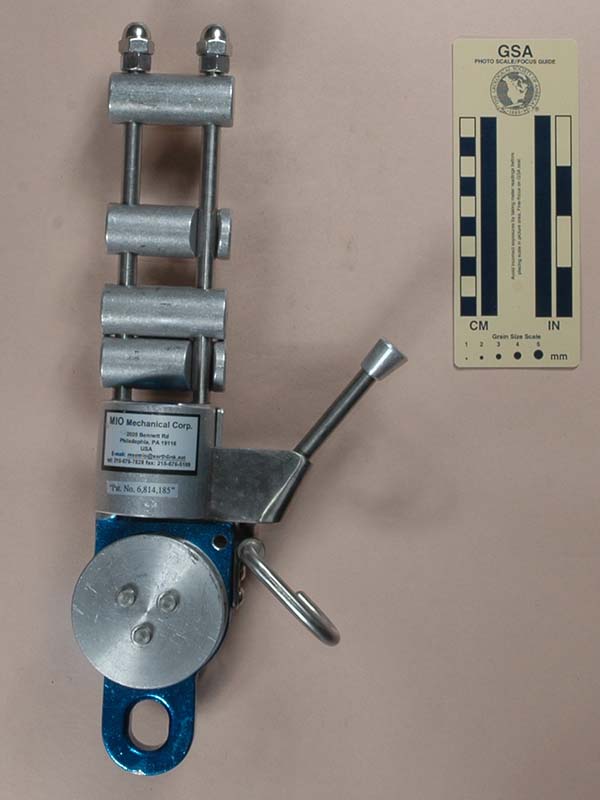
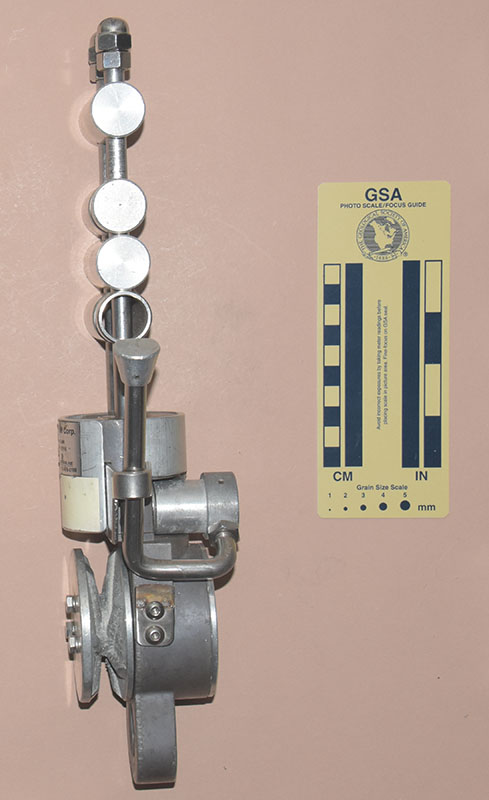
MIO-R, Version A
(#1057)
Technical Details
I acquired my MIO-R, Version A from CWC Supply in 2007.
My Mio Mechanical MIO-R, Version A rack is 358 mm. tall, 157 mm. wide, 85 mm. thick, and weighs 2160 g.
The MIO-R adds a centrifugal overspeed device to the basic
design of the MIO-R2, so I shaded the common part of the following
description in gray:
The MIO-R consists of an upper four-bar
rack portion, a central lever brake control assembly,an
overspeed assembly, and a lower eye.
The rack portion consists of two 175 mm.
tall, 9.5 mm. diameter stainless steel rods screwed into the top
of the aluminum brake assembly housing. The rods are separated
by 29 mm. There are four 61 mm. long, 25 mm. diameter
solid aluminum brake bars. These top and third bar are drilled
but not slotted, so they do not open. The second and fourth bars
are slotted, and hinge on the rod furthest from the brake lever.
A stainless steel hex nut and a stainless steel acorn nut on each
rod hold the bars in place.
The lever brake housing is a 63 mm. tall quasi-cylindrical section. The
upper 54 mm.
are 53.7 mm. in diameter, the remainder 58.4 mm. A 10 mm.
rope groove cuts through the upper 53.7 mm. portion, sloping
down and left until it intersects the chordal cutout.
The rear of the upper cylinder has a
28 mm. round-end milled slot. This slot accepts a 9.6 mm.
shaft that serves as an axle and a 38 mm. long, 25.3 mm./31.8 mm.
diameter stepped bushing that serves as a mount for the brake
lever. There is a washer between the bushing and main body of
the device. A 9.6 mm. diameter, 132 mm. long lever screws
into a bushing mounted on the shaft. The lever bends forward 90°
and then upward at a second, 80°
bend. The end of the lever has an 18 mm. tall, 12.7 mm./20.3 mm.
diameter tip shaped like the frustum of a cone with one side removed.
A moderately strong spring forces the lever outward, where a bend
in the stainless steel plate stops its travel.
The front end of the lever axle shaft
passes through a stainless steel plate screwed to the front of
the cylindrical section (at another cutout), where it is welded
to a D-shaped cam. The lever spring holds the cam against the
rope. Squeezing the lever toward the central column rotates the
cam away from the rope.
Finally, there is an 8.5 mm. spring-loaded
cover retaining pin on the side opposite the lever.
Below the upper cylinder and lever assembly is slightly larger
cylindrical section with one side removed, which intersects a
74 mm. diameter, 44 mm. long horizontal cylinder that
holds the overspeed device. The overspeed device has a cast aluminum
V-groove sheave with six internal ribs. Three screws attach the
sheave to an internal centrifugal clutch. Details of the clutch
are not visible without disassembling the device. The inner surface
of the V-groove intersects one of the screw holes, obviously not
by intent. The opposite side of the overspeed housing is sealed
with a 3.4 mm. thick aluminum plate held in place by three
screws.
There is a hook attached to the side of the overspeed housing,
underneath the control lever. The hook is made from 7.9 mm.
stainless steel rod. It pivots in a cylindrical hole made by bending
a piece of 19 mm. by 3.2 mm. stainless steel into a
loop. The pivot end of the hook is reduced in diameter, and a
nut and two washers hold it in position. The distal end extends
outward, bends 90° downward, then curves back up to form a
30 mm. wide, 48 mm. high hook. The rope leaving the
overspeed sheave should pass through this hook.
A 45 mm. wide, 21 mm. thick tab extends below the
overspeed housing to form the eye for clipping in.
The cover is made from 3.0 mm. sheet
aluminum rolled into a near-cylinder, with a 12.7 mm. gap
for inserting the rope. The cover is 63.6 mm. long and its
internal diameter is 54.1 mm. A subrectangular cutout near
the bottom (adjacent to the rope entry groove) allows the cover
to clear the lever assembly. A beveled 9.1 mm. hole aligns
with the cover retaining pin. The cover has a small screw that
engages an inverted L-shaped slot in the lever brake housing.
This keeps the cover attached to the device. The cover does not
move smoothly, probably because the blue paint on the lever brake
housing causes the cover to stick.
The side of the eye is stamped with the serial number "737."
The cover has two stickers. The smaller
sticker says "Pat. No. 6,814,185" (with quotes). The
larger reads as follows:
MIO Mechanical Corp.
2020 Bennett Road
Philadelphia, PA 19116
USA
E-mail: msemio@earthlink.net
Tel: 215-676-7828 fax:215-676-5199
This is quite a bizarre rack. Most cavers and climbers might
think that the MIO-R2 is an odd design, but the overspeed on the
MIO-R is a step beyond strange - for us. Many of my comments on
the MIO-R2 apply to the MIO-R as well, so I will concentrate on
the overspeed device here.
Naturally, the overspeed device makes the MIO-R much larger
than the MIO-R2. Is it worth it? For my caving and climbing, of
course not, but for window washers, it may very well justify itself.
Their job involves working with both hands while peeping into
people’s windows. This is not the same as rappelling another virgin
pit while exploring a new cave, or rapping off a first ascent.
Spending entire days just hanging around can lead to inattention,
as can having both hands occupied.
Does it work? According to the manual (this time, 14 unnumbered
pages), the overspeed device will lock at about 7 to 7.5 ft/s
(just over 2 m/s) within about 0.4 s, giving a stopping distance
of about 3 feet (1 meter). The maximum dynamic load imposed with
recommended ropes would be on the order of 750 to 800 lbf (3.5
kN). I don't have the laboratory equipment to verify these numbers,
but my own tests are consistent with these results.
[ Top
| MIO-R2, v. A
| MIO-R2, v. B
| MIO-R2, v. C
| MIO-R, v. A
| Return to Racks
]
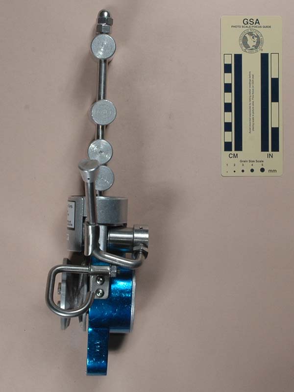
MIO-R, Version B
(#3049)
Technical Details
I acquired this rack from Brian Woodruff in 2021.
Version B is 357 mm. tall, 136 mm. wide, 81 mm. thick, and weighs 1970 g.
Version B differs from Version A as follows:
- When I received this rack, the upper posts only had acorn nuts, and these were not even finger tight. I added hex nuts like the other racks on this page have, and tightened everything appropriately.
- The fourth brake bar is made from 2.2 mm. wall thickness stainless steel. Since the top of this bar is countersunk in the same way as the aluminum bars, I presume the stainless bar is original.
- The cam design is different. This one consists of a cylindrical knob with a milled slot. The cam proper is a piece of 6 mm. steel pinned into this slot. The nose of the cam is rounded.
- The hook is missing, but there is a remnant of the loop that would have held the hook. Heat discoloration and broken welds on the remnant suggests that the hook was originally present and later removed by a previous owner.
The side of the eye is stamped with the serial number "1534."
The cover has two stickers. The lower sticker is faded and cannot be read. The
upper sticker matches the one on Version A.
The serial number indicates that this is the latter of my two versions. Here are my views on the changes:
- Relying on acorn nuts alone is not a good idea, since one cannot verify that they are fully on just by looking. I added hex nuts for safety. Most likely, there were hex nuts at one time, but these were lost or removed by a previous owner.
- I do not see a need for mixing stainless steel and aluminum bars. I prefer aluminum over stainless steel as on bar can be notched to keep the rope centered. Some people dislike aluminum bars because they leave marks on their pretty clean ropes. The marks have never been shown to do any rope damage, and I never found a cave that didn't get my rope dirty.
- Both cam designs work, but I prefer the new one. The steel insert will wear well, but it is starting to show some surface rust.
- I assume that this rack was retired from service because the hook was damaged and had to be removed. The hook guides the rope so that the brake spool will operate properly, so losing the hook removes this "safety" feature.
[ Top
| MIO-R2, v. A
| MIO-R2, v. B
| MIO-R2, v. C
| MIO-R, v. A
| MIO-R, v. B
]