Overview
I never gave these descenders names. I can number them in chronological
order, so I figure I can call them Figure __ descenders, filling
in the blank with the number.
I designed all of these descenders in the early 1970s, but
until I bought my milling
machine, I had no practical way to make models to test. Even
then, I delayed until my sister and I found a large sheet of 6061-T6
aluminum scrap in a dumpster where she worked. It was buried under
a ton of furniture (literally), but she talked the maintenance
men into digging it out for her. After that, I was ready to make
chips and make descenders.
|
 |
Warning:
Do not try making descenders at home.
You will die. |
|
|
[ Top
| Fig. 2
| Fig. 3
| Fig. 4
| Fig. 5
| Fig. 6
| Fig. 7
| Fig. 9
| Fig. 0
| Return to Plate Descenders
]
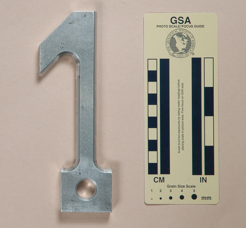
Figure 1
(#1075)
Technical Details
I made my Figure 1 in 2007 by milling a piece of ½" (12.7 mm.) 6061-T6 aluminum alloy plate. The resulting Figure 1 is 173 mm. tall, 62 mm. wide, 13 mm. thick, and weighs 167 g.
My first design received its inspiration from the Peck
Hook that I saw illustrated in Alan Blackshaw’s 1968 book,
Mountaineering, from Hill Walking to Alpine Climbing.
The descender is a simple wrap device, but the long shaft allows
the wraps to spread out more than they do in a simple carabiner
wrap rappel. Unfortunately, the helical wraps cause the user
to spin rapidly, just like they do when using a Patten’s
Hook (which I didn't learn about until 1972).
[ Top
| Fig. 1
| Fig. 3
| Fig. 4
| Fig. 5
| Fig. 6
| Fig. 7
| Fig. 9
| Fig. 0
| Return to Plate Descenders
]
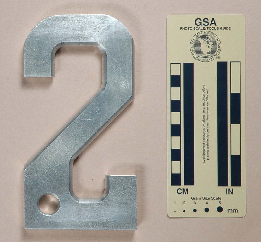
Figure 2
(#1076)
Technical Details
I made my Figure 2 in 2007 by milling a piece of ½" (12.7 mm.) 6061-T6 aluminum alloy plate. The resulting Figure 2 is 175 mm. tall, 91 mm. wide, 13 mm. thick, and weighs 325 g.
I did not like the spin created by my first idea, so I thought
that I could reduce the spin by tilting the shaft. A horizontal
shaft would eliminate the spin but cause the rope to bend too
sharply, so I decided to compromise and place the shaft at an
angle. In the process, I enlarged the hook at the top for security,
and added a lower hook for tie-offs. This was an improvement,
but there was still more spin than I liked.
[ Top
| Fig. 1
| Fig. 2
| Fig. 4
| Fig. 5
| Fig. 6
| Fig. 7
| Fig. 9
| Fig. 0
| Return to Plate Descenders
]
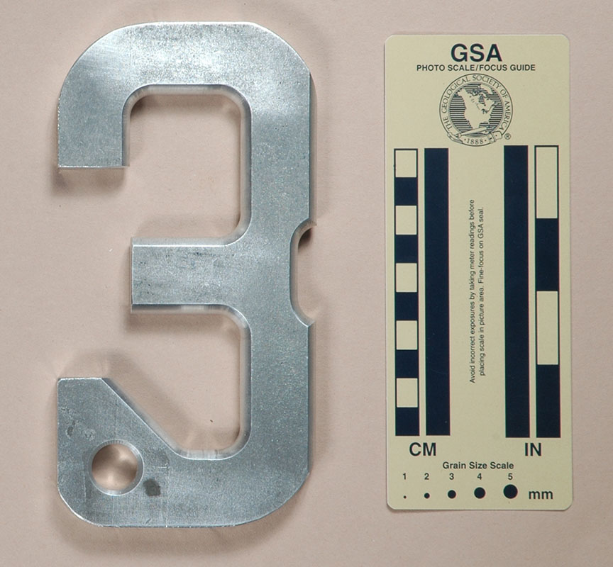
Figure 3
(#1077)
Technical Details
I made my Figure 3 in 2007 by milling a piece of ½" (12.7 mm.) 6061-T6 aluminum alloy plate. The resulting Figure 3 is 175 mm. tall, 90 mm. wide, 13 mm. thick, and weighs 320 g.
My third descender returned to a vertical shaft, but I kept
the large hooks introduced in the second design. If I couldn't
eliminate the spin, maybe I could counter it by wrapping the rope
in one direction at the top and another at the bottom. The central
bar serves as a direction reverser, but I always worried about
the rope slipping off the bar.
[ Top
| Fig. 1
| Fig. 2
| Fig. 3
| Fig. 5
| Fig. 6
| Fig. 7
| Fig. 9
| Fig. 0
| Return to Plate Descenders
]
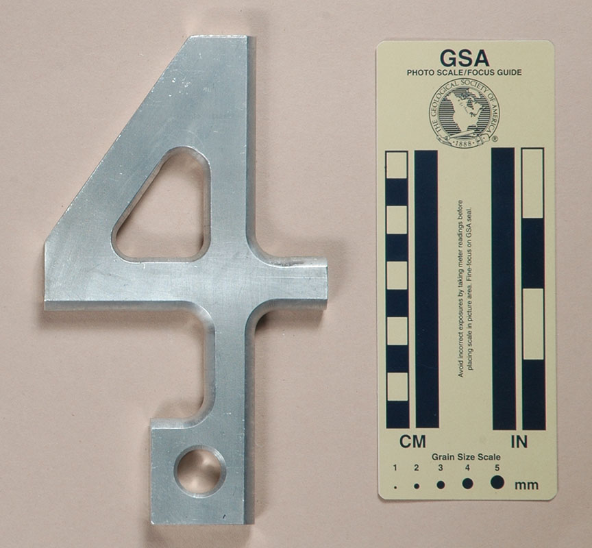
Figure 4
(#1078)
Technical Details
I made my Figure 4 in 2007 by milling a piece of ½" (12.7 mm.) 6061-T6 aluminum alloy plate. The resulting Figure 4 is 175 mm. tall, 121 mm. wide, 13 mm. thick, and weighs 239 g.
My fourth descender addressed the security issues present in
the third design. In this descender, the user pushes a bight through
the hole and around the shaft. The horizontal extension on the
right helps increase the average bend radius around the lower
shaft.
[ Top
| Fig. 1
| Fig. 2
| Fig. 3
| Fig. 4
| Fig. 6
| Fig. 7
| Fig. 9
| Fig. 0
| Return to Plate Descenders
]
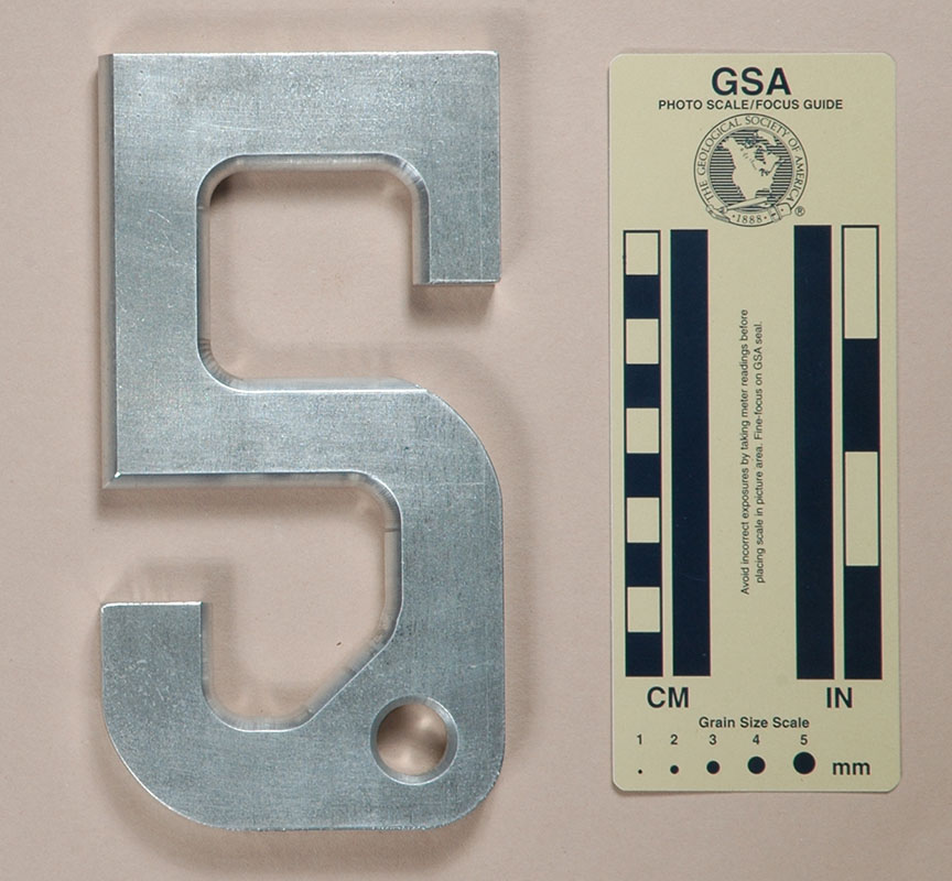
Figure 5
(#1079)
Technical Details
I made my Figure 5 in 2007 by milling a piece of ½" (12.7 mm.) 6061-T6 aluminum alloy plate. The resulting Figure 5 is 173 mm. tall, 90 mm. wide, 13 mm. thick, and weighs 342 g.
My fifth design works more like a brake
bar rig, but it does so with no moving parts. Like most single
brake bar devices, the friction is low and the rappel fast, and
once more, I don't trust the rope to stay where it should.
[ Top
| Fig. 1
| Fig. 2
| Fig. 3
| Fig. 4
| Fig. 5
| Fig. 7
| Fig. 9
| Fig. 0
| Return to Plate Descenders
]
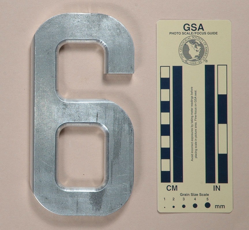
Figure 6
(#1080)
Technical Details
I made my Figure 6 in 2007 by milling a piece of ½" (12.7 mm.) 6061-T6 aluminum alloy plate. The resulting Figure 6 is 173 mm. tall, 88 mm. wide, 13 mm. thick, and weighs 339 g.
My sixth try returned to the idea two designs earlier of passing
a bight though a hole, but rather than passing it around the attachment
post prior to clipping in, I added a hook at the top left. The
user clips into the large hole, then pulls a bight through the
same hole and loops it over the hook. The Longhorn
uses a similar idea.
[ Top
| Fig. 1
| Fig. 2
| Fig. 3
| Fig. 4
| Fig. 5
| Fig. 6
| Fig. 9
| Fig. 0
| Return to Plate Descenders
]
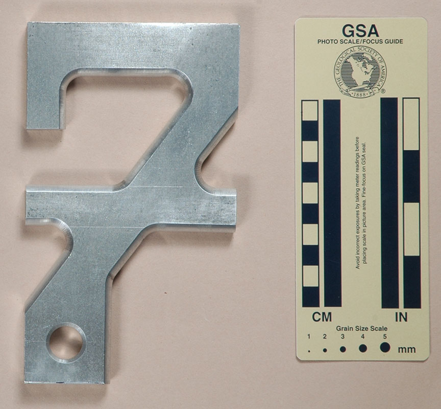
Figure 7
(#1081)
Technical Details
I made my Figure 7 in 2007 by milling a piece of ½" (12.7 mm.) 6061-T6 aluminum alloy plate. The resulting Figure 7 is 173 mm. tall, 102 mm. wide, 13 mm. thick, and weighs 330 g.
My seventh resembled the second, except I added a cross bar
to spread the coils, and eliminated the lower tie-off hook. It
still spins.
My eighth design was another attempt to pull a bight through
a hole, but the resulting design was so obviously absurd that
no one would ever consider using it. It is so bad that I refuse
to show it here.
[ Top
| Fig. 1
| Fig. 2
| Fig. 3
| Fig. 4
| Fig. 5
| Fig. 6
| Fig. 7
| Fig. 0
| Return to Plate Descenders
]
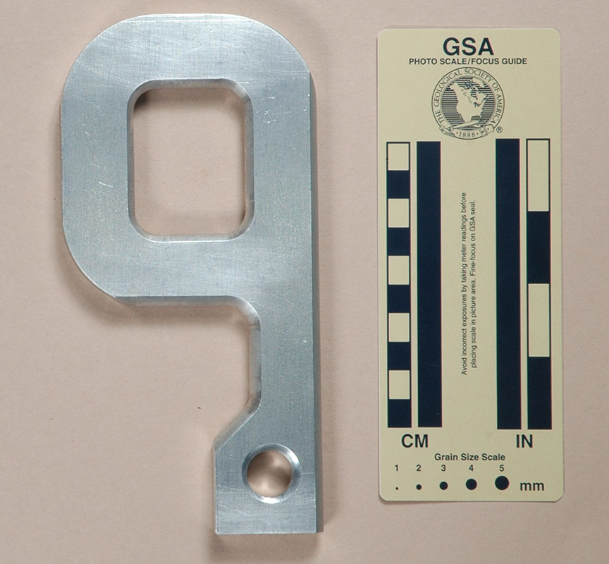
Figure 9
(#1082)
Technical Details
I made my Figure 9 in 2007 by milling a piece of ½" (12.7 mm.) 6061-T6 aluminum alloy plate. The resulting Figure 9 is 181 mm. tall, 90 mm. wide, 13 mm. thick, and weighs 294 g.
My ninth idea was much like the fourth, except I enlarged the
hole and eliminated the horizontal extension on the right-hand
side. It work on flexible rope but tends to be rough on stiff-lay
braided ropes.
[ Top
| Fig. 1
| Fig. 2
| Fig. 3
| Fig. 4
| Fig. 5
| Fig. 6
| Fig. 7
| Fig. 9
| Return to Plate Descenders
]
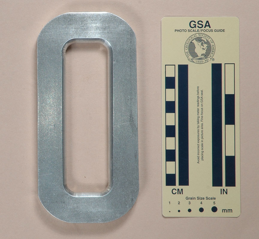
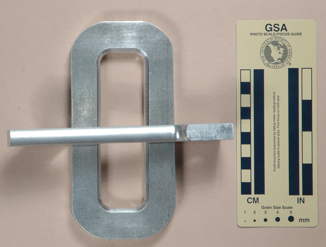
Figure 0
(#1083)
Technical Details
I made my Figure 0 in 2007 by milling a piece of ½" (12.7 mm.) 6061-T6 aluminum alloy plate. The resulting Figure 0 is 173 mm. tall, 82 mm. wide, 13 mm. thick, and weighs 323 g.
My tenth idea uses two pieces. The first was salvaged from
my first design, and the second was a ring. By lying the first
across the ring, you have another brake
bar rig. Clip into the ring.
|
|
Do
not try to use the "0" piece without the "1"
or you will find yourself rappelling on nothing! |
|
|
These are not all of my early designs. I have 26 more to make
when I find the time.
[ Top
| Fig. 1
| Fig. 2
| Fig. 3
| Fig. 4
| Fig. 5
| Fig. 6
| Fig. 7
| Fig. 9
| Fig. 0
]